Last March a lot of 2 mL crimp vials came back from a stability study with a 4.1% RSD on triplicate injections of the same standard, against a method limit of 2.0%. The septa were fine, the crimps were fine, the instrument was fine. The problem was the vial neck: the bore ID had drifted from a 6.00 mm nominal to 6.18 mm on the middle of the mold’s cavitation set, and the autosampler needle was occasionally grazing the shoulder on its way down. That is a 180 µm excursion, roughly three times the tolerance band the drawing allowed, and it was invisible on every certificate of conformance because the Cpk for that dimension had never been calculated. This is what analytical testing dimensional tolerance capability actually looks like when it goes wrong, and why I now insist on capability data, not conformance data, before any mold goes into production.
A certificate of analysis tells you that a sample of parts fell inside the print. It does not tell you how much room was left. A dimension running at 5.98 mm against a 6.00 ± 0.05 mm spec passes inspection every time, and it is also one process drift away from failing every time. Capability is the measure of how much of the tolerance band the process actually consumes, expressed as a ratio of the band width to six sigma of the process output.
For analytical consumables I use three numbers and I want all three on the PPAP:
- Cp: the potential capability, band width divided by 6σ. It ignores centering. A Cp of 2.0 with a mean sitting 0.04 mm off nominal is a bad process wearing a good number.
- Cpk: the capability after accounting for how far the mean sits from the target. This is the number that matters. For a vial neck bore or a septum thickness, I will not release a mold below Cpk 1.33, and I prefer 1.67 on any dimension that touches the needle path or the seal.
- Ppk: the same calculation using overall variation rather than within-subgroup variation. Ppk tells you what the customer will actually experience across lots and shifts. A gap between Cpk and Ppk of more than 0.3 is a warning that the process is drifting between subgroups, usually because of mold temperature or resin lot changes.
I have seen suppliers quote Cpk from a 30-piece study run in a single hour on a single shift. That number is fiction. A defensible capability study for a multi-cavity mold runs at least 25 subgroups of 5 parts, sampled across all cavities, across at least three production runs, with the mold opened and closed between runs. Anything less and you are measuring the machine, not the process. If a supplier cannot produce that, the honest answer is that they have not measured capability at all, and you should treat the dimension as uncontrolled.
What each process can actually hold, and where it stops
The tolerance a molding process can hold depends on the material, the wall section, the gate location, and the number of cavities. The table below is what I have seen hold up in production, not what a molder will quote you on a first phone call. The quoted numbers are always optimistic by roughly a factor of 1.5.
| Process | Typical achievable tolerance (mm) | Best case on a well-controlled dimension (mm) | Where it fails |
|---|---|---|---|
| Injection molding, PP or PE, small part | ±0.10 | ±0.05 | Shrinkage variation across cavities; warpage on thin walls |
| Injection molding, PP or PE, dimension across flow | ±0.15 | ±0.08 | Anisotropic shrink; flow-direction vs cross-flow differ by 0.3 to 0.6% |
| Injection molding, COC or COP (cyclic olefin) | ±0.08 | ±0.03 | Moisture sensitivity; drying variance shifts shrink |
| Injection blow molding, LDPE bottle | ±0.50 | ±0.25 | Parison temperature; wall thickness varies with blow ratio |
| Compression molding, PTFE septum or liner | ±0.13 | ±0.05 | Preform weight; sintering cycle; spring-back after demold |
| Extrusion, PTFE tubing | ±0.10 on OD | ±0.05 | Draw-down ratio; die swell; cure oven tension |
| Machining from rod or billet | ±0.025 | ±0.010 | Thermal growth in the part; tool wear across a run |
Two things about that table. First, tolerance is not a single number per process; it is a number per dimension, and the same mold will hold ±0.05 mm on a dimension in the direction of flow and ±0.15 mm across it. Second, the values assume a controlled shop. A molder running without a drying log and without mold temperature control on every cavity is not holding any of these numbers, whatever the quote says.
This is why I treat the chromatography vial as a dimensional assembly rather than a molded part. The neck bore, the shoulder angle, the crimp ring OD, and the bottom radius all have to hold simultaneously, and they interact. A neck bore that is in tolerance but a shoulder that is 0.1 mm high will still produce needle strikes.
The four dimensions that are genuinely hard to control
Most of a vial or a liner is easy. A competent molder holds the overall height and the body OD without breaking a sweat. The trouble concentrates in four places, and if you are auditing a supplier these are the four you measure.
Neck bore and concentricity
The neck bore controls needle guidance. On a 2 mL vial the nominal is 6.00 mm with a working tolerance of ±0.05 mm, and the concentricity of the bore to the body OD has to be within 0.10 mm TIR. Concentricity is the killer because it is a derived dimension: it depends on core pin alignment, and core pins walk. A mold that has run 400,000 shots without a core pin check will have concentricity drift that no single-cavity dimensional check will catch. Measure it on a shadowgraph or an optical comparator, not with calipers.
Septum thickness and compression set
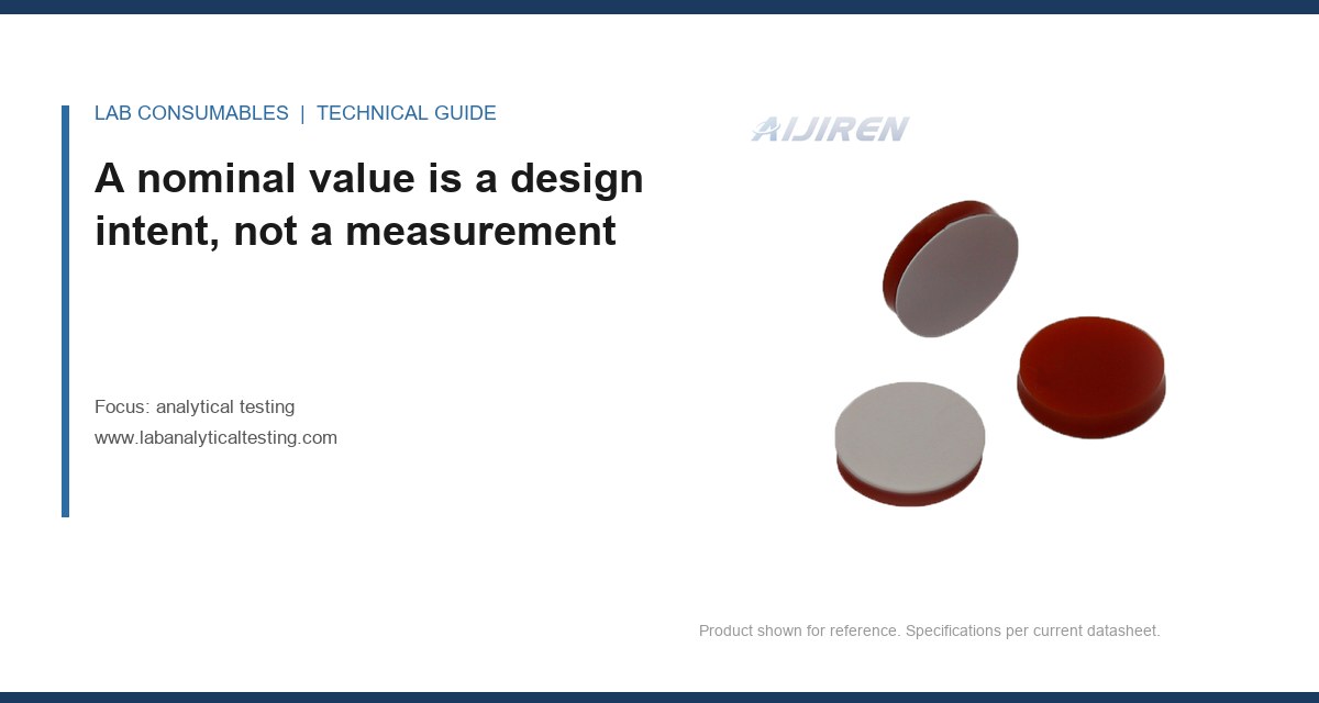
A silicone/PTFE septum is nominally 3.0 mm thick, tolerance ±0.13 mm, and the thickness is the least of it. What matters is compression set after crimping. A septum that measures in tolerance at 3.0 mm but has a compression set of 25% will leak after 24 hours under a crimp cap because it never recovers. I have seen a lot pass dimensional inspection at 3.02 mm average and fail a leak test at 30 minutes because the silicone was under-cured. Thickness is necessary and not sufficient.
Crimp ring OD and the sealing land
The crimp ring is where the cap grabs. The OD has to sit inside the 11 mm crimp dimension with a tolerance that holds the cap in place without over-compressing the septum. The sealing land, the flat annular face that presses on the septum, is where the actual seal happens, and its flatness is the dimension nobody measures. A land that is 0.05 mm out of flat will seal on one side of the vial and leak on the other. This is a mold finish problem as much as a dimensional one, and it is the reason I ask for a surface finish of Ra 0.8 µm or better on any sealing face.
Bottom radius and autosampler seating
The bottom radius determines how the vial sits in the autosampler tray and how far the needle travels before it contacts the septum. A radius that is 0.2 mm off changes the needle penetration depth, and on a short-penetration method (some Agilent and Thermo autosamplers run penetration depths in the 22 to 24 mm range) that is enough to cause coring or partial injection. This is the dimension that shows up as “the autosampler is misbehaving” when the autosampler is fine.
If you are sourcing across the HPLC vial range, ask for the capability report on these four dimensions specifically. A supplier who can only give you the height and the OD is telling you which dimensions they control and which they hope you will not ask about.
How capability is actually measured, and how it gets faked
The measurement system has to be capable before the process can be. A gauge R&R on a 6.00 mm bore with a two-point bore gauge typically comes back at 20 to 30% of tolerance, which is marginal. If the gauge R&R is above 30%, the capability number you calculate is measuring the gauge, not the part. Fix the gauge first: use pin gauges or an air gauge for bores, an optical comparator for concentricity, and a drop indicator on a granite plate for flatness. Calipers on a molded part are a waste of everyone’s time.
The fakes I have caught:
- Capability calculated on a single cavity. A 16-cavity mold has 16 processes. The capability that matters is the worst cavity, not the average.
- Capability calculated after sorting. If the supplier 100% inspects and pulls the outliers before the study, the Ppk is meaningless. Ask for the raw run chart.
- Capability calculated on a dimension that was tool-corrected to nominal. A dimension that has been hand-tuned to dead center on the mean will show a beautiful Cpk and will drift on the next tool wear cycle. Ask when the tool was last corrected and how much steel was moved.
- Capability calculated with the wrong sigma. Using the within-subgroup sigma when the process is drifting between subgroups inflates Cpk. Compare Cpk to Ppk; if the gap is large, trust Ppk.
This is the same discipline that USP <1058> and the general chapter on analytical instrument qualification push for, applied to the physical part instead of the instrument. The analytical testing discipline of qualifying a system before you trust its output applies to a mold as much as to an HPLC.
Two field cases where the dimension was the whole story
Case one: the 4.1% RSD that was a neck bore
The symptom was intermittent high RSD on triplicate injections, always on the same autosampler position, always on vials from one lot. The instrument passed its system suitability. The septa passed puncture testing at 10 punctures with no coring. What identified it was a bore gauge study across 30 vials from the lot: mean 6.09 mm, range 6.02 to 6.18 mm, Cpk 0.41. The cavity that produced the high side had a worn core pin. The fix was a core pin replacement and a re-qualification run of 125 parts across all cavities, which brought the bore to a mean of 6.01 mm and a Cpk of 1.58. The lot was quarantined, the RSD came back to 1.2%, and the supplier now reports bore capability per cavity on every lot.
Case two: the septum that passed thickness and failed leak
A PTFE-faced silicone septum lot measured 2.98 mm average thickness, comfortably inside a 3.00 ± 0.13 mm spec, and failed a 24-hour leak test on 8 of 40 vials. The measurement that identified it was compression set per ASTM D395 Method B: 31% set after 22 hours at 100°C, against a specification of 20% maximum. The silicone was under-cured, and the thickness was a red herring. The fix was a cure time increase of 90 seconds on the press cycle and a compression set test added to the incoming inspection. The lot was rejected. Thickness is the dimension everyone checks and the one that tells you the least.
Both cases share a pattern: the dimension that failed was not the dimension on the certificate. That is the entire argument for capability data. Conformance sampling catches the parts that are out. Capability data catches the process that is about to put them out.
A supplier audit checklist with numbers
When I qualify a molder for analytical consumables, I bring a checklist and I do not accept “we will send it later.” The numbers below are the ones I will not move on.
- Cpk ≥ 1.33 on all functional dimensions, ≥ 1.67 on needle-path and sealing dimensions, calculated from at least 25 subgroups of 5 across all cavities and three runs.
- Gauge R&R ≤ 30% of tolerance on every dimension in the control plan, with the gauge identified by make and model.
- Mold temperature control on every cavity, logged, with a recorded range of ±3°C across the cycle. No exceptions.
- Resin drying log with dew point and residence time for hygroscopic resins (COC, COP, PC). A missing log is a fail.
- Dimensional report per lot with the mean, range, and Cpk per cavity, not a single pass/fail per dimension.
- Compression set ≤ 20% (ASTM D395 Method B, 22 h at 100°C) on every septum lot, reported as a number.
- Crimp seal integrity verified at a defined crimp force; I specify 1.5 to 2.0 N·m equivalent on the crimper setting and a pull-off test at 24 hours.
- Surface finish Ra ≤ 0.8 µm on sealing faces, measured with a profilometer, not eyeballed.
- Traceability from lot number to cavity number to resin lot to press and shift.
If a supplier pushes back on the per-cavity requirement, that is your answer. A molder who knows their process will have the data. A molder who does not will negotiate. The chromatography products market is full of both, and the price difference between them is usually smaller than the cost of one failed stability study.
The dimensions that move after the part is molded
Capability at the press gate is not capability at the customer. Two things move a molded part after it leaves the mold: relaxation and moisture. A COC vial that measures 6.00 mm at the press will measure 6.02 mm after 30 days of relaxation if the mold was packed too hard. A polypropylene part will grow or shrink 0.1 to 0.3% depending on ambient humidity. This is why I require capability to be demonstrated on aged parts, at least 72 hours after molding, and why I want the supplier to state the conditioning protocol. A capability study run on parts measured hot off the press is a study of a part that does not exist yet.
The same applies to PTFE. A compression-molded septum that measures 3.00 mm at demold will measure 3.05 mm after 48 hours of spring-back. If your tolerance is ±0.13 mm and the process is centered at nominal at demold, you have given away 40% of your band to relaxation before the part ever sees a crimper. Center the process low and let it relax into the band, or widen the spec. Those are the only two honest options.
What I actually recommend
Specify capability, not conformance. Put a Cpk requirement of 1.33 minimum and 1.67 on functional dimensions directly into the purchase specification, name the four hard dimensions (neck bore, concentricity, septum compression set, crimp land flatness), and require per-cavity reporting on every lot. Require the gauge R&R, the aging protocol, and the mold temperature log as part of the PPAP. Then audit once a year against the same numbers.
The decision rule is simple: if a supplier cannot show you a Cpk for a dimension that touches the needle or the seal, treat that dimension as uncontrolled regardless of what the certificate says. A certificate of conformance is a statement about the parts in the box. Capability is a statement about the parts in the next box. For analytical work, the next box is the one that ruins your run.
For reference material on the instrument side, Agilent publishes autosampler needle geometry and penetration specifications in its GC columns and accessories documentation, Thermo Fisher covers sample handling tolerances in its chromatography and sample handling resources, and Restek’s technical resources are useful for septum and liner compatibility. On the regulatory side, EPA SW-846 is where the holding-time and container requirements that make dimensional drift expensive actually live.
References & further reading
Related resources from our lab consumables network:
- Analytical Testing at labanalyticaltesting.com
- Chromatography Vial at chromvials.com
- Hplc Vial at hplcvialfactory.com
- Chromatography Products at chromatographyforsale.com
External references and standards: